Three-Decker Structural Renovations
| . Posted in News - 0 Comments
This article gives an inside look at an ongoing gut renovation of a three-decker, particularly one that needed structural repairs. The building was constructed circa 1890 and followed a “two-and-a-half” floorplan, with a pitched as opposed to flat roof.
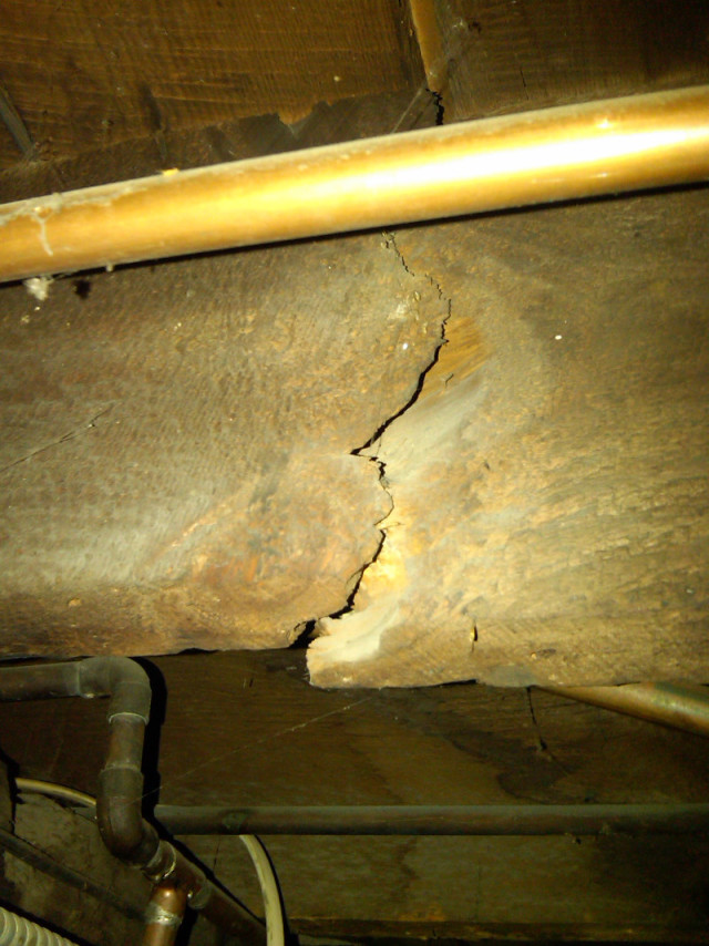
Cracked floor joist under the first floor sagging area.
A Grim Engineer’s Report
A structural engineer reviewed the property for non-conformity in 2009. The kitchen floors sagged as much as three inches from exterior wall to the center, where washer/dryer hookups had been cut. The third floor sagged more than the second, which sagged more than the first.
A first-floor joist visible from the basement was cracked in the affected area. The central carrying beam in the basement was also cracked, in this case, where a previous generation’s plumber had drilled a pipe. Lally columns had been added to attempt to shore up this beam.
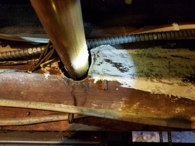
Central carrying beam in basement with 2” hole drilled for plumbing.
During the tour, the engineer was friendly, saying that the building was just “lightly built” and would last a while yet. The written report was far more serious, using wording like “extremely under-designed” and “a substantial number of improprieties.”
Following the engineer’s advice, joint compound was placed in the various cracks to monitor growth. No growth was detected in the basement for the next nine years. Higher up, rare loud pops were heard by occupants in the middle of the night, and one piece of trim detached from a second-floor kitchen door.
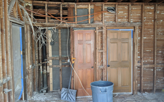
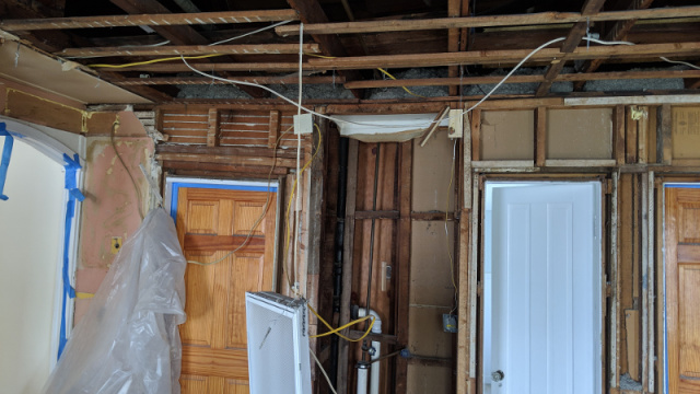
First floor load carrying wall showing large deflection from left side to center door, no header, and misaligned studs.
The building kitchens remained un-updated until 2018, when the first-floor renter moved out at the end of a multi-year tenancy. The needed cosmetic renovation was to add stone countertops and new flooring, but given the structural issues, it would not have been guaranteed to succeed. The rest of the building was cleared for a partial gut. (The remaining renters were offered either temporary relocation or cash for early keys.)
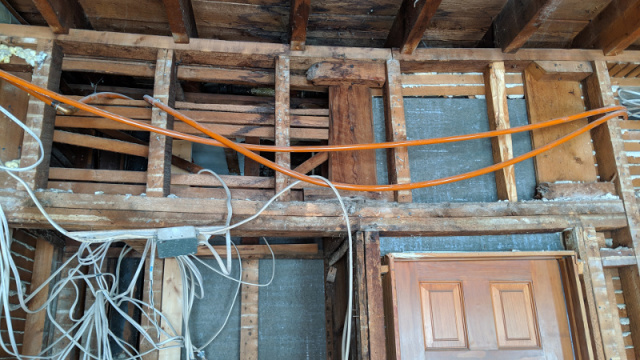
Close-up of first floor load carrying wall. Orange is PEX heat pipe for baseboards. White is wires prior to demo.
Demolition Offers no Comfort
Exploratory holes confirmed which walls were load-bearing, but until demolition it was not known how underdesigned the structure was. The first-floor load-bearing wall included, from left to right, a washer-dryer cutout, a bathroom door, and a bedroom door. This wall was visibly deflected.
Third floor showing same pattern of sag.
The deflection was attributed to two factors beyond the cracked and sagged main carrying beam. First, the wall was built without a header beam, which would today be considered necessary. Second, the studs were not point-loaded continuously up through the structure. Instead of stud over stud, two key studs around the bathroom door were ended in the center of the 2x4’s over the doors.
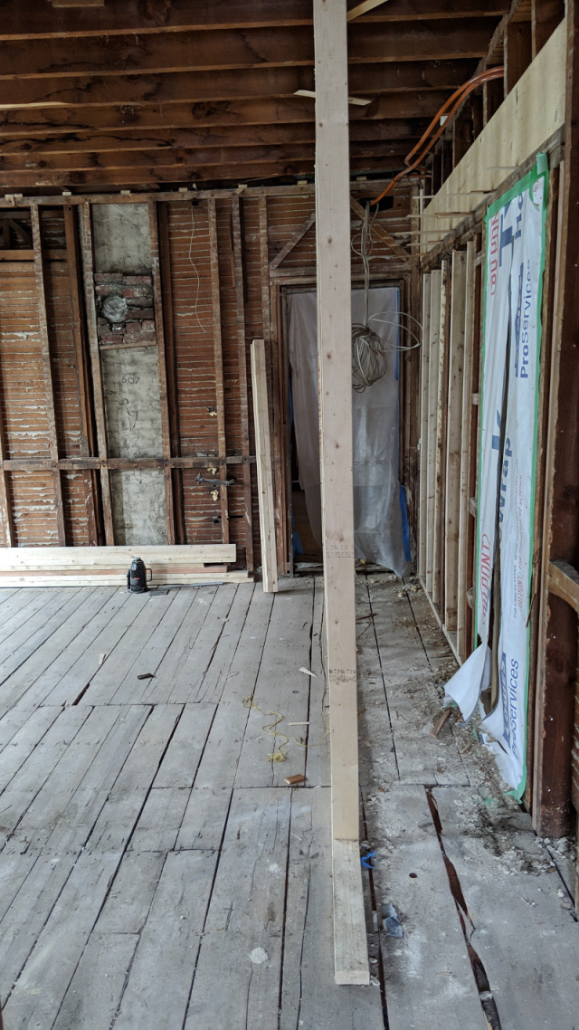
Side view of temporary wall on second floor.
This pattern continued on the second floor and third floors, which had identical load bearing walls. The subfloor was deflected downward along with the beams, and the sag stacked with each floor off the basement.
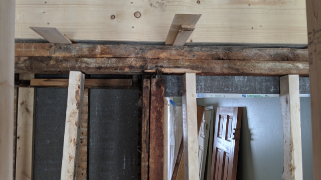
Close-up of shims used to level new header during install.
Jacking, Headers, and Springboard
The plan devised was to point-load all three walls from the carrying beam to the attic using temporary 2x4’s. The main carrying beam in the basement would be raised just under an inch. Each floor would rise with it, more or less. Each floor would receive additional shims to correct the increasing sag higher up. The subfloor would have to be removed and replaced.
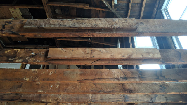
View from second floor up through third floor after third floor subfloor removed. Original joists were cracked, and boards sister across a short span showed a previous owner’s attempt to correct the failure.
Intensive effort was made during the jacking process to minimize disruption to plaster and tile in the unaffected portions of the building. Other structural members were observed for unwanted deflection and reinforced. The building went up and came down in small stages repeatedly as adjustments were made until finally it was raised the full measure without unwanted side effects.
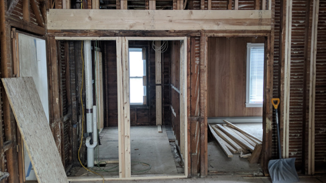
Once the central carrying beam and walls were more or less in their final position, temporary walls were built and used to hold the joists while they were detached from the walls and upgraded with new headers (over the doors) and a new springboard (exterior wall).
Second floor joists sisters and resting on new exterior springboard.
Sistering
The “smiling” or sagging joists were now well attached but unsuitable for new construction. They needed to be sistered with new LVL joists to provide a new level floor. Additionally, 2x4” strapping would be placed underneath to provide pipe chases on either end and level ceiling below. In this way, the sagging joists could be totally enveloped in true material, supply and heating pipes could be moved between bays without cutting joists, and the new kitchens would be fully level.
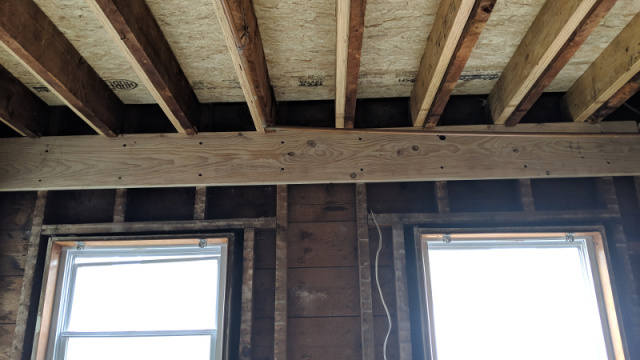
First floor header installed and doorways trued. Temporary walls removed.
The final floor was blocked between joists for added stiffness. The structure, which previously had been described as “lightly built,” now felt solid and level. New three-quarter inch subfloor could be installed and rough plumbing and electrical could begin.
The renovation is ongoing, and permits have not been closed. When the renovation is closed and permits are issued, willing contractors, engineers, owner, and municipality will be credited with their contributions.